ROCK BREAKAGE AND BLAST DESIGN CONSIDERATIONS IN OPENPIT
PARTHA DAS SHARMA
1. Explosives Energy Release and Rock Breakage: Mechanism of rock breakage while release of Explosives energy upon detonation and other relevant points are discussed below:
- When an explosive charge is detonated, chemical reaction occur which, very rapidly changes the solid or liquid explosive mass into a hot gases.
- This reaction starts at the point of initiation where detonator is connected with explosives and forms a convex like shock wave (Compressive wave) on its leading edge that acts on the borehole wall and propagates through the explosive column.
- Ahead of the reaction zone are undetonated explosive products and behind the reaction zone are expanding hot gasses.
| Understanding theory of detonation of explosives– The self-sustained shock wave produced by a chemical reaction was described by Chapman and Jouquet as a space. This space of negligible thickness is bounded by two infinite planes – on one side of the wave is the unreacted explosive and on the other, the exploded gases as shown in the Fig. 1.There are three distinct zones:a) The undisturbed medium ahead of the shock wave,b) A rapid pressure at Y leading to a zone in which chemical reaction is generated by the shock, and complete at X,c) A steady state wave where pressure and temperature are maintained.This condition of stability condition for stability exists at hypothetical X, which is commonly referred to the Chapman- Jouquet (C-J) plane. Between the two planes X and Y there is conservation of mass, momentum and energy.

Fig – 1
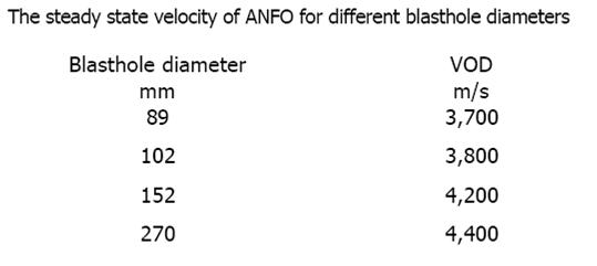
Velocity of detonation (VOD) of explosive is function of Heat of reaction of an explosive, density and confinement. The detonation pressure (unit in N/m2) that exists at the C-J plane is function of VOD of explosives. The detonation of explosives in cylindrical columns and in unconfined conditions leads to lateral expansion between the shock and C-J planes resulting in a shorter reaction zone and loss of energy. Thus, it is common to encounter a much lower VOD in unconfined situations than in confined ones.
Rock breakage by Detonation and Interaction of explosive energy with rock – There are three sources of generation of fragments in mines: (a) Fragments formed by new fractures created by detonating explosive charge, (b) In-situ blocks that have simply been liberated from the rock mass without further breakage and (c) Fragments formed by extending the in-situ fractures in combination with new fractures.
Rock fragmentation by blasting is achieved by dynamic loading introduced into the rock mass. The explosive loading of rock can be separated into two phases, the shock wave and gas pressure phase (Fig.2).
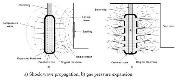
Fig. 2
|
- Rapid the detonation process, the quicker the energy release from explosives mass, in the form of a shockwave followed by gas pressure, is applied to the borehole wall. In other words, faster the detonation velocity of the explosive, quicker is the energy applied to the borehole wall, and for a shorter time period.
- Conversely, with a slower detonation velocity, the energy is applied more slowly, and for a longer time period. The degree of coupling between the explosive and the borehole wall will have an effect on how efficiently the shockwave is transmitted into the rock.
- Pumped or poured explosives will result in better transmission of energy than cartridge products with an annular space between the cartridge and the borehole wall.
- Again, the pressure that builds up in the borehole depends not only upon explosive composition, but also the physical characteristics of the rock.
- Strong competent rock will result in higher pressures than weak, compressible rock.
- When the shock wave reaches the borehole wall the fragmentation process begins.
- This shock wave, which starts out at the velocity of the explosive, decreases quite rapidly once it enters the rock and in a short distance is reduced to the sonic velocity of that particular rock.
- Most rock has a compressive strength that is approximately 7 times higher than its tensile strength, i.e. it takes 7 times the amount of energy to crush it as it does to pull it apart.
- When the shockwave first encounters the borehole wall, the compressive strength of the rock is exceeded by the shockwave and the zone immediately surrounding the borehole is crushed.

Fig. 3
- As the shockwave radiates outward at declining velocity, its intensity drops below the compressive strength of the rock and compressive crushing stops.
- The radius of this crushed zone varies with the compressive strength of the rock and the intensity of the shock wave, but seldom exceeds twice the diameter of the borehole.
- However, beyond this crushed zone, the intensity is still above the tensile strength of the rock and it causes the surrounding rock mass to expand and fail in tension, resulting in radial cracking.
- The hot gas following the shockwave expands into the radial cracks and extends them further.
- This is the zone where most of the fragmentation process takes place.
- However, if the compressive shockwave pulse radiating outward from the hole encounters a fracture plane, discontinuity or a free face, it is reflected and becomes a tension wave with approximately the same energy as the compressive wave.
- This tension wave can possibly “spall” off a slab of rock (see figure 3).
- This reflection rock breakage mechanism depends heavily upon three important requirements:
(a) the compressive wave (and resulting reflected tensile wave) must still be of sufficient intensity to exceed the tensile strength of the rock,
(b) the material on opposite sides of the fracture plane or discontinuity must have different impedances,
(c) the compressive pulse must arrive parallel to, or nearly parallel to, the fracture plane or free face.
- If carried to extreme, when this reflective breakage or “spalling” process occurs at a free face, it can result in violent throw, a situation that is not desirable.
- This can be overcome by designing blasts with burden and spacing dimensions that are within reasonable limits.
- Once the compressive and tensile stresses caused by the shockwave drop below the tensile strength of the rock, the shock wave becomes a seismic wave that radiates outward at the sonic velocity of the material through which it passes.
- At this point, it is no longer contributing to the fragmentation process.
Important points learned through experience:
- Within the range of conventional blasting, the physical characteristics of the rock are more important than the characteristics of the explosives used and can have a greater impact on the success or failure of a blast.
- Final-size fragmentation is usually obtained before any appreciable rock movement or throw occurs.
- Rock can absorb only so much energy and only at a certain maximum rate before it will fail.
- The final displacement of the bulk of the rock is more a function of the duration of the gas pressure than its intensity.
|
2. Contemplation of Blast Design: Blast designing is not a science, but knowledge, experience, studying and analyzing past practices in relation to rock strata & geology etc., makes blaster to achieve perfection. Thus, for a blaster, valuable tool is the file of blast reports that he builds as he gains experience. Not only do these provide evidence of the quality of his work, but they also provide a wealth of information upon which he can draw as future blasting situations develop.
Blast Design: This is meant to be a toolbox for blast design in conventional rock quarrying and open pit mines. This write-up is not meant to give straight answers to the blast design parameters, as every single quarry is unique. However, the general relations between the main blasting parameters; geology, blastability and explosives, will be applicable, and the estimation model is a very good tool for planning test blasts and experiments, and also for adjustments of the blast design when this is necessary for optimising the quarry production line as time progresses.High accuracy throughout the whole blasting process is fundamental for achieving a proper blast result. Various points as success criteria are shown below:
- Planning
- Surveying and marking of holes
- Adjustment of drilling pattern
- Adjustment of specific charge
- Delay times and initiation pattern
- Accurate drilling
- Properly selected stemming material
- Control, documentation and supervision of the work
When optimising quarry operations, it is often difficult to accomplish several elements of improvement simultaneously. It is very important to try one effort at a time and be sure of the conclusions from each single specific adjustment before introducing new adjustments. Elements of improvement must be effectuated according to a mutual superior strategy.
It is important to continuously keep up the process of improvement and always be interested in increasing the workers knowledge and skills about the process. This must be done to gain competence and effectuate the potential long term outlook. It is important to document the results to avoid loss of information if key personnel quit. The sum of improvements will most often be visualised in the form of higher efficiency and lower repair and maintenance costs. Understanding the meaning of the blasting process as a continuous cycle, how the various parameters can be changed to optimize wanted blasting result and how to evaluate the result, is essential when optimizing the quarry processes. |
Before a blaster can design a blast, there are a number of site specific things that he must take into consideration that will have an impact on his design. Blaster should define at least the following items before he undertakes to design a blast:
A. Fragmentation desired:
- Size of digging/handling equipment.
- Size of crushing equipment (if required).
- Rip-rap or dimensional stone desired?
- Size limitations in project specifications?
B. Rock quality/character:
- Hard? Soft? Porous?
- Holes wet? Dry? Variable?
- Joints and slip planes? Bedding planes?
- Voids or other incompetent zones?
C. Site limitations:
- Structures or other property to protect? At what distance?
- Utilities nearby (underground or above ground)?
- Vibration and airblast considerations?
- Integrity of rock to be left in place.
- On-site or off-site vehicle traffic?
- Any other project specification limitations?
D. Safety limitations:
- Adequate protection from flyrock?
- Weather – is lightning a possibility?
- Any nearby electrical hazards?
- Any nearby RF (radio) hazards?
- Impact hazards from rock fall?
- Ventilation needed?
- Traffic control required?
- The impact of potential misfires. (How isolated is the site?
- Is double-priming advisable to minimize misfires?)
E. Equipment / materials limitations:
- Drilling equipment – size, condition.
- Steel lengths available – depth of blast.
- Explosives (including detonators) – Type, size, quantity available.
- Adequate magazine site nearby?
- Blasting mats available if needed?
- Other blasting accessories?
Apart, investigate the area thoroughly and identify those items that will affect your blast or be affected by your blast and design accordingly.
3. Blast design Calculations and empirical formulas: In designing a blast, following principles should be kept in mind:
- Explosive force functions best when the rock being blasted has a free face toward which it can break.
- There must be an adequate void or open space into which the broken rock can move and expand (or swell).
- To properly utilize the energy available, the explosive product should be well-confined within the rock.
If a blast is lacking in one or more of these above principles, the results will generally be less than desired.
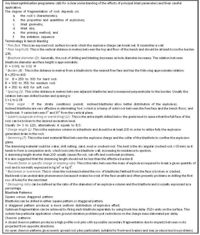
Empirical formulas developed by Ash with few modifications are discussed here. Following symbols and definitions are given in relation to the equations discussed:
- D = Diameter (in inches) of the explosive in the borehole.
- B = Burden, the distance (in feet) from a charge to the nearest free face in the direction that displacement will most likely occur.
- S = Spacing, the distance (in feet) between two holes, measured perpendicular to the corresponding burden.
- L = Hole length or depth (in feet).
- J = Sub-drilling length (in feet), the depth that the hole extends below the anticipated grade or floor.
- T = Stemming height or collar distance (in feet). The top portion of the hole containing inert materials intended to prevent premature ejection of gasses.
- H = Bench or face height (in feet).
Note: In these relationships, the Burden and Spacing dimensions are the “shot” burden and spacing, which may or may not be the “drilled” burden and spacing. Changes in the initiation timing scheme will determine the difference (see Fig. 4). Moreover, it is important to understand that the blast parameters listed are inter-related and that changing one parameter will have an impact on others.

Fig – 4
Discussion:
- The burden that can be successfully blasted depends largely upon the strength of the rock and the amount of energy that is placed behind it.
- The amount of energy that can be loaded is dependent upon the hole volume, or diameter; hence, the hole diameter and rock strength largely determine the burden distance.
- Often, the hole diameter has already been established by the drilling equipment on hand.
- If it hasn’t, the optimum hole diameter should be selected based upon considerations such as fragmentation desired, bench height, rock quality, etc.
- In selecting hole size, smaller hole diameters and tighter patterns will result in better fragmentation, but will increase drilling, loading and product costs.
- Taller bench heights will allow larger hole diameters and larger burdens and less drilling and blasting cost.
- Also, if the material to be blasted is blocky, it is quite likely that some blocks may emerge intact unless smaller hole diameters and tighter patterns place explosives within them.
- Once the hole diameter has been established, burden distance can be selected.
The following ratios can be used as first approximations in designing blasts. Bear in mind that the ratios will usually have to be adjusted as one learns more about how the particular rock reacts when blasted:
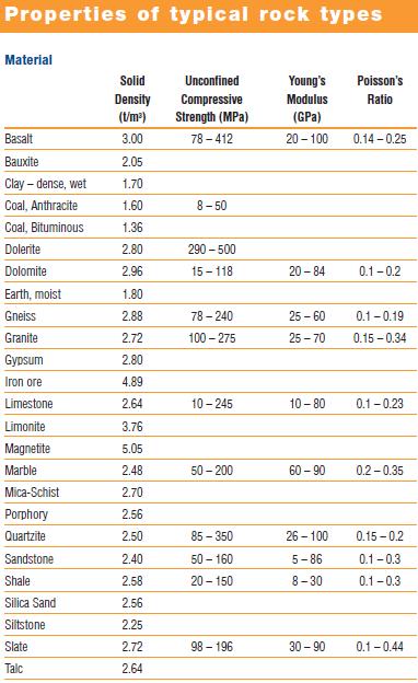
- Burden = roughly 24 to 36 times the explosive diameter.
- Using AN/FO at a specific gravity of 0.82 g/cc:
i) light rock (2.2 g/cc density) = 28 x diameter
ii) medium rock (2.7 g/cc density) = 25 x diameter
iii) dense rock (3.2 g/cc density) = 23 x diameter
- Using Slurries, Emulsions, etc at a specific gravity of 1.20 g/cc:
i) light rock (2.2 g/cc density) = 33 x diameter
ii) medium rock (2.7 g/cc density) = 30 x diameter
iii) dense rock (3.2 g/cc density) = 27 x diameter
- Spacing = 1.0 to 2.0 times the burden
i) holes shot instantly by row = 1.8 – 2.0 x burden
ii) large diameter holes shot sequentially = 1.2 – 1.5 x burden
iii) small diameter holes shot sequentially = 1.5 – 1.8 x burden
- Bench height = 1.5 to 4 times the burden, or possibly higher
Bench height is usually limited on the low end by the height of the stemming column required and its limiting effect on the amount of explosive that can be loaded, and limited on the high end by the height of the digging equipment (for safety reasons).
- Sub-drilling = 0.1 to 0.5 times the burden
i) flat bedding plane at toe = 0.0 – 0.1 x burden
ii) relatively easy toe = 0.1 – 0.2 x burden
III) medium toe = 0.2 – 0.4 x burden
IV) difficult toe (vertical bedding) = 0.5 x burden
- Stemming column length = 0.5 to 1.3 times the burden
I) Increased multiplier if drill cuttings are used for stemming and/or holes are wet.
II) Decreased multiplier if stone chips are used for stemming and/or holes are dry.
III) For very cautious blasting (no throw or flyrock allowed):
IV) Stemming = up to 36 times the hole diameter, possibly more
V) Stemming length between decks to be fired on separate delays:
VI) Deck length: dry hole = 6 times the hole diameter
VII) Deck length: wet hole = 12 times the hole diameter
Note:
A certain amount of caution must be exercised when selecting values. For example, too small a burden would result in excessive forward throw, while too large a burden would probably yield inadequate fragmentation with possible excessive upward throw. In a similar manner, too wide a spacing would result in loss of interaction between detonating charges, while too little spacing could cause partial cancellation of explosive forces and could contribute to excessive vibration.
The type of stemming material plays an important part in confining the gas generated from explosives detonating in the hole. Angular crushed stone chips are preferred. Round pebbles, dirt and water are not and should be avoided. Most of the time, drill cuttings are used, but they can be marginal.
If sub-drilling is not sufficiently deep, the result will be high bottom. Excessive sub-drilling, however, is wasteful of drilling labor and explosive energy.
Other factors such as initiation timing and direction have an impact and will have to be considered.
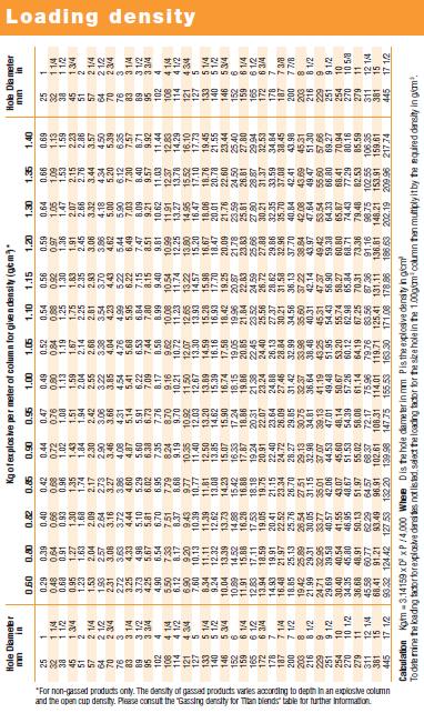
POWDER FACTOR. In construction blasting, powder factor (PF) is expressed as quantity (unit mass) of explosive per unit volume of material blasted. For mining, it is usually expressed as quantity of explosive per ton of material (or sometimes tons of material per unit mass of explosive).

Fig – 5
DELAY TIMING: Very seldom is a conventional blast set off where all charges are detonated in the same instant. Usually there is a specific time interval and direction or directions for delaying the charges.
For tunnels, drifts and shafts where there is no free face parallel to the axis of the holes, longer delay periods are utilized. These are intended to provide sufficient time delay for the fractured rock from the initial holes to be expelled so that there is room for the rock blasted by the following holes to expand.
In construction and in surface mining, millisecond delays are used between charges in a blast. There are several basic reasons for doing so:
- To assure that one or more free faces progress through the shot, providing a consistent burden.
- To enhance fragmentation between adjacent holes.
- To reduce ground vibration and airblast.
- To provide a means of directing the heave or displacement of the blasted material.

V, V1, V2 Patterns :These Pattern are far superior, to row delays. These result in superior fragmentation due to reduce hole burdens and increased spacing at the time of hole initiation and also due to inflight collision of broken rock during its movement. Thedelayed action of holes in the back row reduces over break ensuring increased wall stability.
The best available pattern is one where the holes are drilled (staggered) on a equilateral triangle pattern. This in a drilled spacing to burden ratio of approximately 1.16. It has been observed that an effective spacing (Se) to Burden (Be), ratio of about 3.5 is achieved with holes drilled on an equilateral triangle grid and fired using a V1 initiation sequence.
Drilling (staggered) equilateral triangular pattern require more operator skill and supervision as compared to in-line patterns. Clear marking of the hole positions in advance by a responsible person would help the drillers immensely. Fig. gives various delay patterns discussed above.

Fig.6
|
Theoretically, it is possible to “fine tune” the timing of a blast to achieve ideal results. Although rather sophisticated electronic detonators are available, standard millisecond (ms) delay systems can be obtained that will generally provide enough flexibility and a sufficient range of timing for most applications. There may be specific applications where extremely accurate delay detonators are necessary, but for most conventional blasting situations, the standard units are satisfactory. In many cases, a small amount of scatter in the times can actually be beneficial in reducing vibration, as long as the accuracy is adequate to prevent overlap, or near overlap, of detonation times.
- A. The delay time between individual holes in a row:
i) The delay time between holes in a row should be between 1 ms and 5 ms per foot of burden, with 3 ms yielding good results in most instances.
ii) Where airblast is a problem or potential problem, the delay time between holes in a row should be at least 2 ms per foot of spacing.
iii) This will result in a blast progression along the face or along a row of holes that is approximately half the speed of sound (or less) and reduces the low frequency airblast generated by face area movement or by surface area mounding.
iv) Where possible, corner holes at the end of rows should be given extra delay time because of the greater degree of fixation of the rock in those locations requires more time for the rock blasted by previously fired adjacent holes to move away.
- B. Delay interval between rows:
i) The delay interval between rows should be from two to three times longer than the delay interval between holes in a row.
ii) The last row in the shot should often be delayed slightly more than preceding rows.
iii) This serves to allow rock in previously fired rows time to move out and tends to reduce back-break in the rock behind the blast.
Note: Regardless of the delay times selected for holes in the same row or for the delay time between rows, it is absolutely essential that the delay intervals be sufficiently short that there is a buffer zone between a detonating hole and detonators that have yet to see their initiating signal. This is usually accomplished by using longer down-hole delays.
An additional hazard can exist where delay times (compared to burden and spacing) are excessively long, causing cutoffs of the initiation system or powder columns due to ground shift. Again, this needs to be analyzed on a case by case basis and accounted for during blast design.
Direction of heave or throw: It is generally possible to control the direction of heave of the material from a blast through application of the initiation system timing sequence. In fig -5, an arrow shows the directions of most logical heave when the various delay sequences shown are used. The numbers in the various figures represent the initiation sequence. Shooting row by row will generally lay the muck out in front of the shot. Shooting with a V-cut timing pattern will usually result in a muck pile that tends to mound up in the center in front of the shot.
The method of digging out the shot will usually determine which is preferable.
The direction of maximum vibration (all other things being equal) will theoretically be in the direction opposite from the direction of heave.
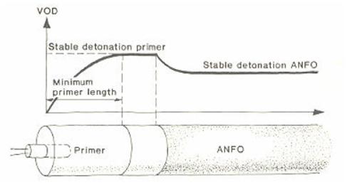
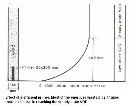
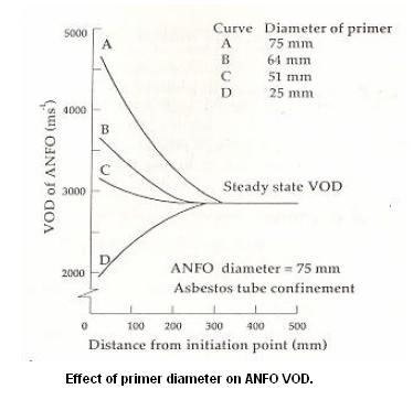
Location and Orientation of Primer: In most instances the priming charge will be located at the bottom of the hole. If the priming charge was located at the top of the powder column, the energy would break through the surface earlier in the explosion process, gasses would vent sooner and much of their contribution to the fragmentation process would be lost.
The orientation of the detonator in the priming charge should be such that the detonator is pointing in the direction of the explosives column. I.e. the detonator would be pointing upward in a bottom-priming charge and downward in a top-priming charge.
FRAGMENTATION: Primary fragmentation occurs during the detonation phase. The shock waves exceed the compressive and the tensile strength capacity of the rock, and the rock is crushed and pulverized close to the drill hole, and radial cracks will be created out from the hole to a certain extent (equal to 4 – 5 times the hole radius). The gas pressure will penetrate new cracks and existing fissures and joints, loosening the rock mass and throwing it out and over the bench floor.
Secondary fragmentation breakage starts with the throw when fragmented material accelerates out from the bench. The secondary breakage is attributed to:
- Collisions between fragments in the air and between fragments and the bench floor.
- High compressive stress levels and conserved elastic energy in the rock are released when the fragments are loosened from the bench.
The fragmentation varies through the rock pile. See Fig. 7. The coarser fragments originate from the first row and from the uncharged zone in the upper part of the blast.
Controllable factors which influence primary fragmentation:
- Drill hole diameter
- Mass of explosive charge
- Stress waves’ peak values
- Charge distribution in the bench
Secondary fragmentation may be increased by a plough shaped firing pattern. Fragmentation is also influenced by the original fracturing of the rock. This applies both during the detonation and in the following operations, such as loading, transportation, crushing and placing of the rock.

Fig.7
Studies of the rock pile show that:
- The coarsest fractions in the rock pile originates from the shoulder/edge section of the blast, and from the uncharged volume.
- The coarser fractions form a skirt which covers the top of the pile. Increased uncharged length rapidly increases the depth of this top layer.
- Fragmentation of the shoulder section is highly dependent upon the bench top conditions. Terrain blasts normally produce more blocks than previously subdrilled bench floor conditions which originate from an overlying blast. Decreasing the stemming length to reduce the amount of oversized block will not necessarily be a success. Most likely, gas venting will appear resulting in excessive flyrocks.
- The part of the rock pile which originates from the charged part of the blast gives the most fragmented rock.
| BLASTHOLE INCLINATION
Benefits of Inclined Drilling in Surface Mining: In Bench Blasting, inclined drilling extends numerous benefits. These are:
– Better Fragmentation
– Better displacement and swelling of muckpile, as Burden B is kept almost uniform along length of blasthole and angle of projection of the blast increases (Refer fig below).

– Less chances of misfire caused by cutoff from Burden movement.
– Smoother and sounder slop from newly created benches, means, better slope stability of benches.
– Higher productivity of Front-end-Loader and Hydraulic Excavator due to more swelling and relatively lower height of muckpile.
– Less sub-drilling and better use of explosive energy, with the consequent lower vibration level.
– Lower consumption of Explosive per Cum of Rock excavation, as shock wave is reflected more efficiently in the bench toe and possibility of increasing burden size with Less Risk of Toe Appearance. In other words, Toe problem is greatly resolved with Inclined Drilling.
– In Surface Coal Mine, the mineral over-crushing is greatly reduced. |
ROCK MASS FRACTURING: The discontinuities or weakness planes of the rock mass influence the blastability. The weakness planes are recognised by little or no shear strength along the planes. Typical discontinuity features are:
- Systematically fractured rock mass
i) parallel oriented joints and fissures
ii) foliation planes or bedding planes
- Marked single joints
- Filled joints
- Crushed zones and zones with mineral or clay fill
Fracturing is characterised by rate of fracturing (type and frequency) as well as orientation (angle between blast direction and weakness planes). Various rock classification systems can be used to characterize the fracturing of the rock mass. Here we mention RQD, RMR and RMi. They more or less measure the same rock parameters.
The different fracturing parameters can be described as follows:
- “Joints” mean continuous planes of weakness. These joints can be open, e.g. bedding joints in granite, or filled with clay or weak minerals, e.g. calcite, chlorite or similar minerals.
- “Fissures” are planes of weakness which can only be followed over parts of the face. It can be filled joints with low shear strength and bedding plane fissures (partings) e.g. as in mica schist and mica gneiss.
- “Homogeneous rock mass” means massive rock without joints or fissures and may occur in intrusive dikes, sills, batholiths etc.
Increased fissure joint degree gives better blastability. This is typical in regional metamorphic rock types.
Systematically oriented joint sets make the rock more difficult to blast. Large blocks are isolated in the throw without being crushed. Fractured conditions are characteristic for rocks in surface blasting.
BLASTING DIRECTION: Normally the blasting direction is perpendicular to the face of bench face, and it should be adjusted according to the direction of the fracturing. In special cases, the bench face direction may be fixed in a non favourable direction due to topography, quarry borders or strict geometrical demands, as in road cuttings or building sites. In these cases, the firing pattern can be used to control the blast direction in a more favourable direction and improve the blasting result.
Before drilling, the blast direction should be set according to the orientation of the main jointing systems. Fragmentation, backbreak and toe problems are all dependent upon the blasting direction.
Even though optimal fragmentation usually is the most important criterion, consideration of back wall, toe and bench floor must be considered to get an optimal total result. Orientation of the back wall may be along a weakness plane and the blast direction turned close up to the optimal angle.
Quarry management should provide documentation of the main discontinuity systems in operational maps. The blasting results should be followed up according to blasting directions and main fracture systems. The results from these studies will be the foundation for further blast planning and optimal quarry management.
Some of the most common combinations of rock type, fracturing and conventional quarrying blasting results are discussed. These are:
- Anisotropic rock mass with approximately vertical fracturing.
- Anisotropic rock mass with inclined fracturing.
- Rock mass with vertical fracturing and little anisotropy.
- Rock mass with inclined fracturing and little anisotropy.
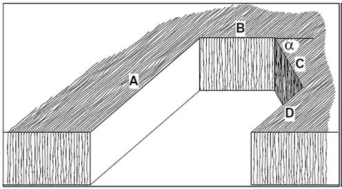
Anisotropy of the rock gives directional dependent rock strength and directional dependent blasting effects. The angle between weakness planes and blast direction is given by the angle α. Blast direction is defined to be perpendicular to the bench wall face. Bench wall direction is described by A, B, C or D.
Anisotropic rock mass with approximately vertical fracturing:
| FACE DIRECTION |
FRAGMENTATION |
BACKBREAK ANDTOE PROBLEMS |
BENCH FLOORUNDERBREAK |
| A |
Medium (1) |
small |
medium |
| B |
Poor (2) |
large |
large |
| C |
medium to good (3) |
small |
medium |
| D |
Medium (1) |
small |
medium |
1. Confined holes in the blast give poor breakage with bench floor underbreaks as a result.
2. Gas venting along schistosity in the walls. Flyrock and blocks is normal, particularly in the first row. Spacing must be reduced in the first row to reduce these problems.
3. Blast direction C is most favourable. The best result will appear with blast direction perpendicular to C and back wall along D. In such rock types, the bench floor conditions often will be the main parameter when designing the drilling pattern.
Inclined fracturing:

| FACE DIRECTION |
FRAGMENTATION |
BACKBREAK ANDTOE PROBLEMS |
BENCH FLOORUNDERBREAK |
| A |
Poor (1) |
Large (2) |
large |
| B |
good |
some |
medium |
| C |
good |
some |
Medium (3) |
| D |
Good (1) |
some |
medium to large |
1. The main problem with inclined schistosity is the fact that the most favourable blast direction (B) is parallel to the strike direction. When firing row by row, the face does not become stiff enough and it will have excessive buckling.
This problem can be solved by using reduced bench height or small diameter drill holes.
2. Some backbreak and backslides on fissures along the schistosity.
3. In fissure fractured rock, C is the most favourable orientation when it comes to blast direction and the back wall.
Independent upon blasting direction, hole deflection may be a considerable problem in inclined schistose rock, resulting in zones with poor fragmentation and bench floor problems.
Approximately vertical fracturing and little anisotropy (Typical rock types are quartzite and granite gneiss):

| FACE DIRECTION |
FRAGMENTATION |
BACKBREAK ANDTOE PROBLEMS |
BENCH FLOORUNDERBREAK |
| A |
good |
little |
medium |
| B |
slightly poor |
Some (2) |
Varying (4) |
| C |
good |
Much (3) |
Little (5) |
| D |
good |
Little (1) |
medium |
1. Little backbreak, even though incorrect alignment of drill holes according to the fracturing direction will give large fall-outs along the weakness planes, even for α < 10°.
2. Rough and uneven back wall. The face gets more uneven with higher fracturing degree, increased drill hole diameter and drill hole pressure. This results in more blocks in front of the rock pile.
3. Maximum backbreak for α = 45°, some larger blocks will occur at the back of the rock pile due to fallouts. Backbreak can be reduced by increasing the uncharged length in the back row.
4. Gas pressure leakages in the face resulting in flyrock, poor fragmentation (especially along the bench floor) and general bench floor problems. Especially in joint fractured rock.
5. Bench floor problems may occur if the first row breaks poorly. A possible way to make this better is to drill along D and fire along C.
Rock with inclined fracturing and little anisotropy:

| FACE DIRECTION |
FRAGMENTATION |
BACKBREAK ANDTOE PROBLEMS |
BENCH FLOORUNDERBREAK |
| A |
Poor (1) |
very large (2) |
large |
| B |
good |
Some |
medium |
| C |
very good |
little |
Medium (3) |
| D |
good |
little |
medium to large (4) |
1. A large amount of block from the uncharged length in exfoliated, joint sheeted rock. If blasting on terrain bench, the top should dip backwards, otherwise many blocks will mix into the charged part of the rock pile. This is definitively the least favourable blast direction in joint fractured rock.
2. Extra subdrilling is necessary to avoid bench floor problems.
3. C is the most favourable orientation if the back wall and the first row breaks properly. If not, less specific charge in the back row and smaller hole spacing in the first row will improve the result.
4. Bench floor problems are reduced with increased subdrilling. Necessary subdrilling depends on dip angle.
To some extent, hole deflection may reduce the fragmentation degree and increase the bench floor problems.
Additional information:


